MPLS – Inter-AS MPLS L3VPN Options (A, B, C)

Comparing Inter-AS MPLS L3VPN Options (A, B, C)

When an L3VPN service needs to span across two different service providers, an Inter-AS L3VPN solution is required. This scenario is common for national or international circuits where a single service provider is not present in both locations. The routers connecting the two autonomous systems (AS) are known as Autonomous System Border Routers (ASBRs) or boundary routers. In this article I will go into the three primary options for connecting L3VPNs across autonomous system boundaries: Option A, Option B, and Option C, highlighting their distinct characteristics, operational mechanisms, and suitability for various deployment scenarios.

Inter-AS L3VPN Options: Overview

The following table summarizes the key differences between Inter-AS L3VPN Option A, Option B, and Option C, drawing from design considerations, scalability, security, and operational complexity 
 
Aspect

Option A

(Back-to-Back VRF)


Option B

(VPNv4 between ASBRs)

Option C

(RR-to-RR VPNv4)

Scalability Least scalable Moderate Highest
Security Most secure Lower Lowest
Resource Utilization High (per VRF state on ASBRs) Moderate Low (ASBRs only exchange loopbacks)
Label Handling No MPLS between ASBRs Yes, via BGP (RFC 3107) Yes, via BGP LU + RT exchange
Complexity Simple More complex Very complex
BGP AF IPv4 per VRF VPNv4 VPNv4 (multihop)
Typical Use Case Small deployments, high security Medium scale, simpler than C Large-scale carriers, scalability focus

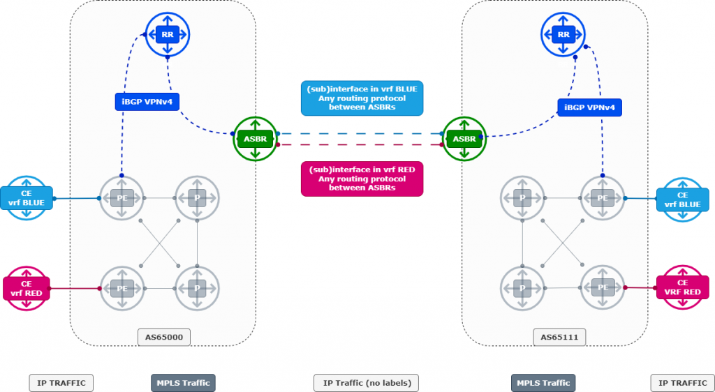
Inter-AS Option A – Back-to-Back VRF

Topology

Theory

Option A is the simplest to understand and deploy. Each provider treats the other as a customer, and the ASBRs host VRFs for every inter-AS VPN. Routing information is exchanged within those VRFs across dedicated interfaces or subinterfaces. Because the ASBRs carry customer traffic and maintain full VRF state, the model is very resource-intensive and scales poorly.

The clear benefit of Option A is its simplicity and strong per-VRF isolation. It gives providers granular control and is also considered the most secure option since the separation between customers is maintained on a per-VRF basis. However, the main drawback is low scalability. As the number of VPNs increases, ASBRs quickly become bottlenecks due to the overhead of maintaining VRFs, policies, and forwarding state for every customer.

Packet Walk


Hop Device Action on Labels Resulting Packet Notes
1 PE1 (AS 65000) Imposes VPN label (e.g., 24000) [VPN L=24000] IP(192.168.3.1) CE1 in VRF RED sends traffic. PE1 pushes VPN label for CE3’s prefix (learned via MP-BGP).
2 P1 (AS 65000 core) Swaps VPN label via LDP [VPN L=24000] IP(...) Core does normal MPLS forwarding within AS 65000.
3 ASBR1 (10.0.0.1) Pops VPN label, forwards as plain IPv4 in VRF RED IP(192.168.3.1) Since the inter-AS link is VRF-aware (subinterface in VRF RED), ASBR1 removes the VPN label and sends raw IPv4.
4 ASBR2 (10.0.0.2) Receives IPv4 in VRF RED, re-imposes new VPN label (e.g., 31000) [VPN L=31000] IP(192.168.3.1) Acts like a PE — assigns new VPN label for CE3’s VRF RED in AS 651111.
5 P2 (AS 651111 core) Swaps VPN label via LDP [VPN L=31000] IP(...) Normal MPLS forwarding in AS 651111.
6 PE2 (AS 651111) Pops VPN label 31000 IP(192.168.3.1) Packet is placed into VRF RED and forwarded to CE3.

Configure

====== AS65000
====== ASBR:


! VRF RED
vrf RED
 rd 65000:1
 address-family ipv4 unicast
  import route-target 65000:1
  export route-target 65000:1

! VRF BLUE
vrf BLUE
 rd 65000:2
 address-family ipv4 unicast
  import route-target 65000:2
  export route-target 65000:2

! Subinterfaces for VRFs
interface GigabitEthernet0/0/0/0.10
 vrf RED
 ipv4 address 10.0.0.1 255.255.255.252

interface GigabitEthernet0/0/0/0.20
 vrf BLUE
 ipv4 address 10.0.0.5 255.255.255.252

! Route-policies
route-policy PASS
  pass
end-policy

router bgp 65000
 address-family vpnv4 unicast
  neighbor 10.0.0.99
   remote-as 65000
   update-source Loopback0
   route-reflector-client
   address-family vpnv4 unicast
    send-community both

 ! VRF RED
 vrf RED
  rd 65000:1
  address-family ipv4 unicast
   neighbor 10.0.0.2
    remote-as 651111
    address-family ipv4 unicast
     route-policy PASS in
     route-policy PASS out

 ! VRF BLUE
 vrf BLUE
  rd 65000:2
  address-family ipv4 unicast
   neighbor 10.0.0.6
    remote-as 651111
    address-family ipv4 unicast
     route-policy PASS in
     route-policy PASS out
====== AS65111
====== ASBR:


! VRF RED
vrf RED
 rd 65111:1
 address-family ipv4 unicast
  import route-target 65111:1
  export route-target 65111:1

! VRF BLUE
vrf BLUE
 rd 65111:2
 address-family ipv4 unicast
  import route-target 65111:2
  export route-target 65111:2

! Subinterfaces for VRFs
interface GigabitEthernet0/0/0/0.10
 vrf RED
 ipv4 address 10.0.0.2 255.255.255.252

interface GigabitEthernet0/0/0/0.20
 vrf BLUE
 ipv4 address 10.0.0.6 255.255.255.252

! Route-policies
route-policy PASS 
  pass
end-policy

router bgp 65111
 address-family vpnv4 unicast
  neighbor 10.111.111.99
   remote-as 651111
   update-source Loopback0
   route-reflector-client
   address-family vpnv4 unicast
    send-community both

 ! VRF RED
 vrf RED
  rd 65111:1
  address-family ipv4 unicast
   neighbor 10.0.0.1
    remote-as 65000
    address-family ipv4 unicast
     route-policy PASS in
     route-policy PASS out

 ! VRF BLUE
 vrf BLUE
  rd 65111:2
  address-family ipv4 unicast
   neighbor 10.0.0.5
    remote-as 65000
    address-family ipv4 unicast
     route-policy PASS in
     route-policy PASS out

Inter-AS Option B – VPNv4 Peering Between ASBRs

Topology

Theory

Option B removes the need for ASBRs to carry individual VRFs by establishing an eBGP VPNv4 session between the boundary routers. Labels are exchanged via BGP (RFC 3107), which allows traffic to remain MPLS-encapsulated across the inter-AS link. Compared to Option A, this reduces configuration overhead on the ASBRs and avoids per-VRF scaling issues.

The main advantage of Option B is improved scalability while still being relatively straightforward to deploy. Because a single VPNv4 eBGP session can carry multiple customers’ routes, the operational burden is lighter. However, Option B introduces complexity around label distribution and next-hop handling, which requires careful configuration. Security is weaker compared to Option A, since VRF separation is no longer enforced at the ASBRs, and providers must rely more on BGP policy control.

Packet Walk


Hop Device Action on Labels Resulting Label Stack Notes
1 PE1 (AS 65000) Imposes two labels [Transport L=16045] [VPN L=24000] Outer = LDP label toward ASBR1. Inner = VPN label allocated by PE2, learned via VPNv4 eBGP exchange between ASBRs.
2 P1 (AS 65000 core) Swaps outer 16045 → 16051 [16051] [24000] Normal LDP transport in AS 65000. Inner VPN label untouched.
3 ASBR1 (10.0.0.1) Swaps outer 16051 → 20010 [20010] [24000] ASBR1 knows VPNv4 routes and their labels (from ASBR2). It preserves the inner VPN label 24000.
4 ASBR2 (10.0.0.2) Swaps outer 20010 → 30077 [30077] [24000] ASBR2 also carries VPNv4 routes. It forwards toward PE2 while preserving the inner VPN label.
5 P2 (AS 651111 core) Swaps outer 30077 → 16012 (PHP) [24000] Penultimate hop popping removes the transport label, leaving only the VPN label.
6 PE2 (AS 651111) Pops inner 24000 IP(192.168.3.1) Looks up 24000 in VRF RED, forwards packet to CE3.

Configure

====== AS65000
====== ASBR:


route-policy PASS
  pass
end-policy

router bgp 65000
 address-family vpnv4 unicast
  retain route-target all
  neighbor 10.0.0.2
   remote-as 651111
   address-family vpnv4 unicast
    route-policy PASS in
    route-policy PASS out
    send-community both
    next-hop-self
====== AS65111
====== ASBR:


route-policy PASS
  pass
end-policy

router bgp 65111
 address-family vpnv4 unicast
  retain route-target all
  neighbor 10.0.0.1
   remote-as 65000
   address-family vpnv4 unicast
    route-policy PASS in
    route-policy PASS out
    send-community both
    next-hop-self

Inter-AS Option C – VPNv4 Peering Between Route Reflectors

Topology

Theory

Option C represents the most scalable approach to inter-AS L3VPNs. In this model, ASBRs no longer carry customer VRF state or VPNv4 routes. Instead, only loopback reachability is exchanged between ASBRs using IPv4 labeled unicast. VPNv4 sessions are established directly between route reflectors (or in some cases PEs) in each AS. This pushes state away from the ASBRs and distributes it across the RR infrastructure, which is generally designed to scale.

The advantage of Option C is scalability. It allows providers to interconnect large numbers of VPNs without overwhelming the ASBRs, making it the preferred design for large carrier environments. On the other hand, it is also the most complex option to implement. Route reflectors must be carefully designed to handle the additional state, and policies must be applied to control route exchange. Security is weaker compared to the other options since providers exchange a much broader set of routes, and leaks are more difficult to contain

Packet Walk


These are the hops from CE device in the VRF RED on the left, towards CE device in the VRF RED on the right.

Hop Device Action on Labels Resulting Label Stack Notes
1 PE1 (AS 65000) Imposes labels [Transport L=16045] [VPN L=24000]

Outer = LDP/LU to PE2 loopback (10.111.111.2).
Inner = VPN label from PE2 for VRF RED.

2 P1 (AS 65000 core) Swaps outer 16045 → 16051 [16051] [24000] Standard LDP label swap toward ASBR1.
3 ASBR1 (10.0.0.1) Swaps outer 16051 → 20010 [20010] [24000] Label learned via BGP LU from ASBR2.
4 ASBR2 (10.0.0.2) Swaps outer 20010 → 30077 [30077] [24000] New LU label toward PE2 loopback.
5 P2 (AS 651111 core) Swaps outer 30077 → 16012 (PHP) [24000] Penultimate hop popping removes transport, leaves only inner VPN label.
6 PE2 (AS 651111) Pops inner 24000 IP(192.168.3.1) Looks up VPN label in VRF RED, forwards to CE3.

Configure

====== AS65000
====== ASBR:

route-policy PASS
  pass
end-policy

router bgp 65000
 address-family ipv4 unicast
  allocate-label all
  neighbor 10.0.0.2
   remote-as 651111
   address-family ipv4 labeled-unicast
    route-policy PASS in
    route-policy PASS out
    
====== RR:
  
route-policy PASS
  pass
end-policy

router bgp 65000
 address-family vpnv4 unicast
  neighbor 10.111.111.99
   remote-as 651111
   update-source Loopback0
   ebgp-multihop 255
   address-family vpnv4 unicast
    route-policy PASS in
    route-policy PASS out
    send-community both
    next-hop-unchanged


====== PE:

vrf RED
 rd 65000:1
 address-family ipv4 unicast
  import route-target 65111:1      
  export route-target 65000:1  
  
  
====== AS65111
====== ASBR:

route-policy PASS
  pass
end-policy

router bgp 65111
 address-family ipv4 unicast
  allocate-label all
  neighbor 10.0.0.1
   remote-as 65000
   address-family ipv4 labeled-unicast
    route-policy PASS in
    route-policy PASS out
    
====== RR:

route-policy PASS
  pass
end-policy

router bgp 65111
 address-family vpnv4 unicast
  neighbor 10.0.0.99
   remote-as 65000
   update-source Loopback0
   ebgp-multihop 255
   address-family vpnv4 unicast
    route-policy PASS in
    route-policy PASS out
    send-community both
    next-hop-unchanged    
    
====== PE:

vrf RED
 rd 65111:1
 address-family ipv4 unicast
  import route-target 65000:1  
  export route-target 65111:1  


Conclusion

Inter-AS MPLS VPN interconnects can be deployed in several ways, each with clear trade-offs.

Option A provides maximum isolation and security but quickly becomes unmanageable at scale.

Option B improves scalability by moving VRFs off the ASBRs but sacrifices per-customer policy control.

Option C achieves the highest level of scalability by limiting ASBR involvement, but it is operationally complex and comes with reduced security.

Ultimately, the choice depends on business drivers, scale, and security requirements. Smaller interconnects may favor Option A, while large carriers often rely on Option C. 

SD-Access under the hood; Locator/ID Separation Protocol (LISP)


SD-Access under the hood; Locator/ID Separation Protocol (LISP)


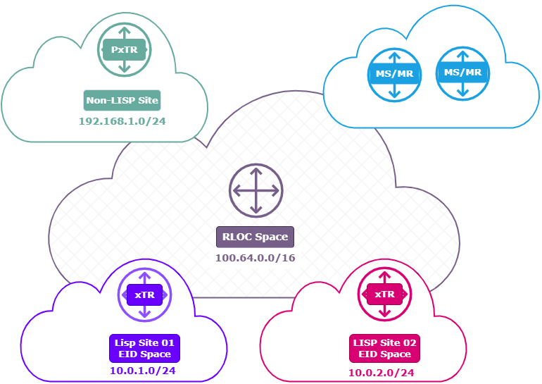
When it comes to Cisco’s software-defined access (SD-Access), one of the key technologies working behind the scenes is Locator/ID Separation Protocol (LISP). At first glance, LISP might seem like just another routing protocol, but it plays a much bigger role. It fundamentally changes how network addressing works by decoupling identity from location. This separation is especially important in SD-Access environments, where flexibility, scalability, and mobility are critical.

In this article, I will break down the funadementals of LISP, the core components that make up its architecture, and how it fits into the SD-Access framework. Whether you’re managing campus networks or diving into next-gen network design, understanding LISP is essential to grasp how SD-Access delivers secure, automated, and policy-driven access.

LISP Fundamentals

Logical View;


Phyical view;

(more…)

Cisco Live Amsterdam 2025

Cisco Live 2025 Amsterdam

Introduction

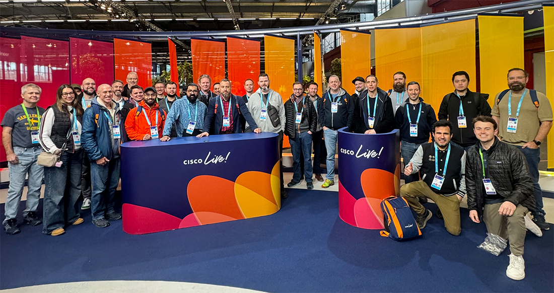
Cisco Live has been on my bucket list for a many years. I heard the stories, watched the streams and VODs and wondered what the event would be like in person. This year Routz facilitated the opportunity and together with a couple colleagues I was able to attend Cisco Live EMEA 2025 in Amsterdam.
My focus from a technology perspective was on SD-Access, Catalyst Center, Service Provider Technologies, Segment Routing, Multi-Domain Segmentation and IPv6. 

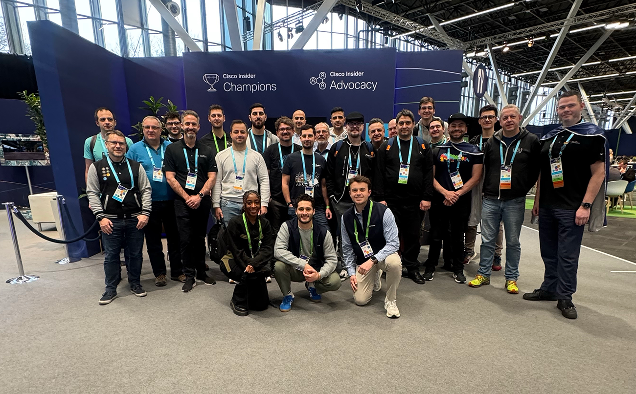
Cisco Champions

Being part of the Cisco Champions made the experience even better because I was able to meet people from our community in person. I got to talk to Champions from America, Iceland, Azerbaijan, Germany, Sweden and many more countries from all over the world. The Cisco Champions gave us access to behind-the-scenes tours before the event started, whisper sessions on many topics and domains, and feedback session with Bonny Shapira who is charge of planning Cisco Live EMEA.

(more…)

IS-IS Redistribution and Route Summarization


Intermediate System to Intermediate System (IS-IS)


Intermediate System to Intermediate System (IS-IS) is a dynamic link-state routing protocol widely used in large-scale networks, especially in service provider environments. In this post I will look at the following IS-IS configurations;

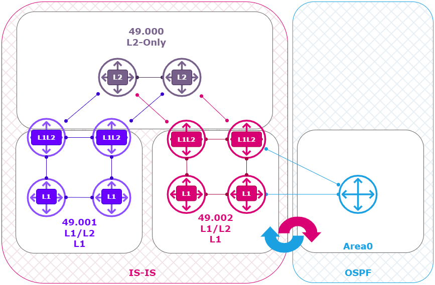
  • Redistribution of OSPF into IS-IS, and the differences between L1 and L2.
  • IS-IS Path selection when L1 and L2 routes are available.
  • How and where to apply IS-IS Route Summarization.

IS-IS Lab Setup


Labs download

The CML Lab is available for download here.

1 – Lab IS-IS Route Redistribution and Summarization

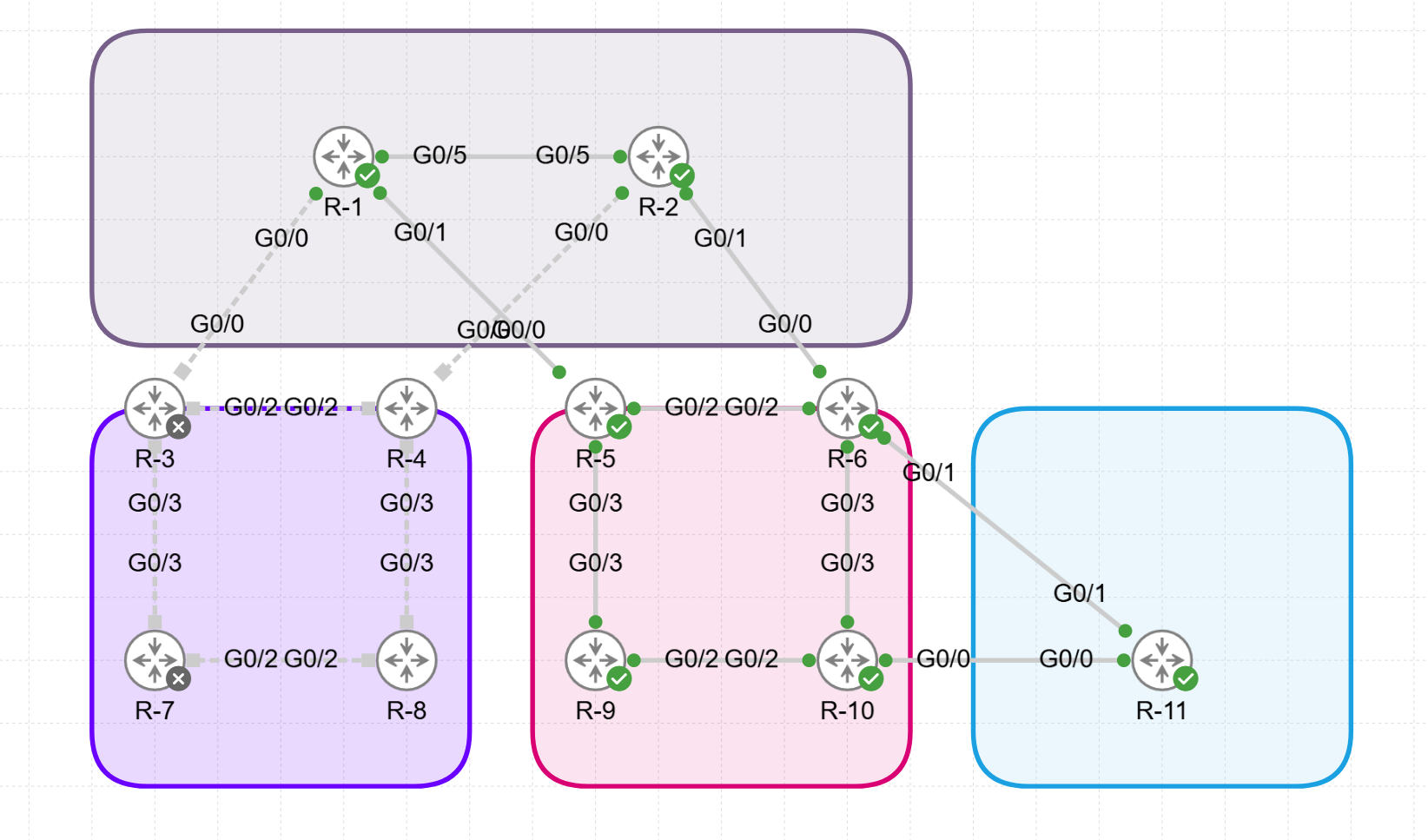
Using Cisco’s Modeling Labs (CML) I build the following IS-IS and OSPF topology:

  • 2 x L2 Router ( Top )  (R1, R2) running XRv with IOS-XR.
  • 2 x L1L2 Router ( left ) (R3, R4) running XRv with IOS-XR.
  • 2 x L1 Router ( left ) (R7, R8) running IOS with IOSv.
  • 2 x L1L2 Router ( Center ) (R5, R6) running XRv with IOS-XR.
  • 2 x L1 Router ( Center ) (R9, R10) running IOS with IOSv.
  • 1 x OSPF Router (R11) running IOS with IOSv.

Logical View:

Physical View:

(more…)

IS-IS – Interlevel Routing


Intermediate System to Intermediate System (IS-IS)


Intermediate System to Intermediate System (IS-IS) is a dynamic link-state routing protocol widely used in large-scale networks, especially in service provider environments. One of its features is interlevel routing, which allows communication between IS-IS levels (Level 1 and Level 2). This post explains IS-IS interlevel routing and provides configuration examples to implement it in practical scenarios.

IS-IS Lab Setup


Labs download

The CML Lab is available for download here.

1 – Lab IS-IS Configuration

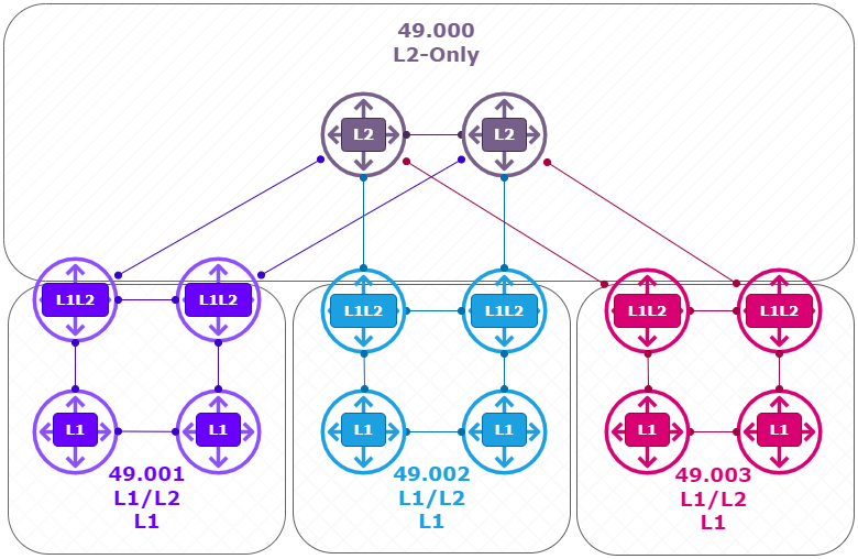
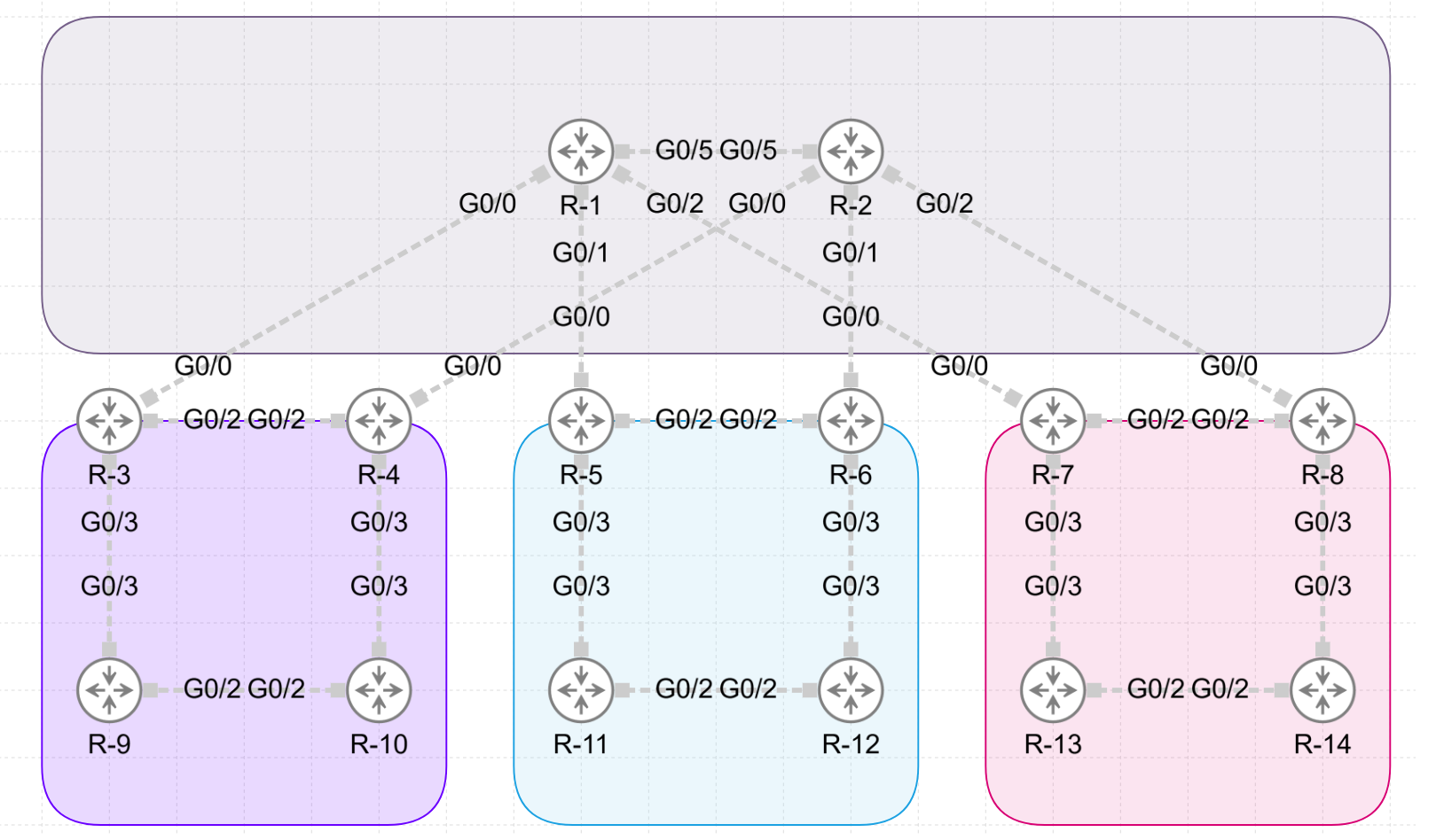
Using Cisco’s Modeling Labs (CML) I build the following IS-IS topology:

  • 2 x L2 Router ( Top )  (R1, R2) running XRv with IOS-XR.
  • 2 x L1L2 Router ( left ) (R3, R4) running XRv with IOS-XR.
  • 2 x L1 Router ( left ) (R9, R10) running IOS with IOSv.
  • 2 x L1L2 Router ( Center ) (R5, R6) running XRv with IOS-XR.
  • 2 x L1 Router ( Center ) (R11, R12) running IOS with IOSv.
  • 2 x L1L2 Router ( Right ) (R7, R8) running XRv with IOS-XR.
  • 2 x L1 Router ( Right ) (R13, R14) running IOS with IOSv.

Logical View:

Physical View:

(more…)

CML 2.7 – Getting started with APIs using Postman

Cisco Modeling Labs 2.7

Cisco Modeling Labs (CML) is a powerful, scalable network simulation platform that enables network engineers, IT administrators, and developers to design, build, and test networks in a controlled environment. The latest version, Cisco Modeling Labs 2.7, introduces new features and enhancements, including an improved REST API that enables seamless automation and integration. In this article, we’ll discuss how to get started with CML 2.7 and use Postman to interact with its API for network automation tasks.

CML API Documentation

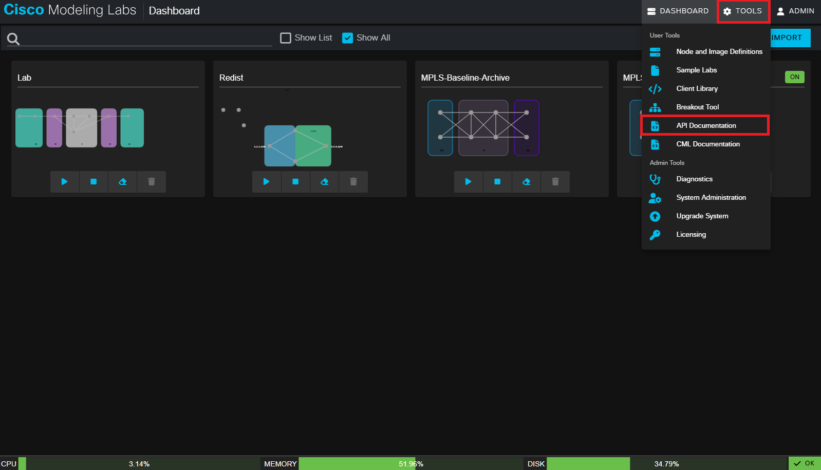
Log in to Cisco Modeling Labs: Go to the CML web interface, typically accessed via your browser.

Find API Documentation: CML’s built-in documentation is available under Help > API Documentation. This provides detailed information on available API endpoints, request formats, and expected responses.

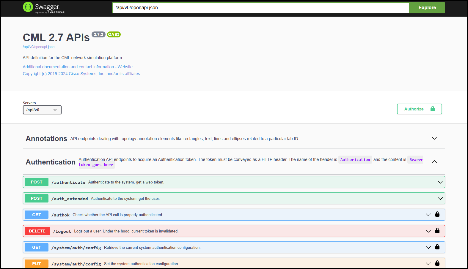
A new page will open with the documentation:

Here you can find all the information on the available CML API calls that you might need. 

(more…)

MPLS – Fast Reroute (FRR) and TI-LFA

What is Fast Reroute (FRR) in an MPLS network?


In an MPLS network with Segment Routing (SR), ensuring rapid recovery from link or node failures is crucial for maintaining high network availability. Cisco’s IOS-XR supports various Fast Reroute (FRR) mechanisms within MPLS Segment Routing environments, including Link Protection, Node Protection, and Topology Independent Loop-Free Alternate (TI-LFA). This article will provide a configuration guide and explanations for these MPLS-SR FRR mechanisms in an MPLS SR-enabled network running OSPF as the Interior Gateway Protocol (IGP).

What is TI-LFA in an MPLS network?


TI-LFA (Topology-Independent Loop-Free Alternate) is a fast reroute (FRR) mechanism in MPLS Segment Routing (MPLS-SR) designed to provide sub-50ms recovery from link or node failures in IP/MPLS networks. Unlike traditional LFA, which relies on specific topological conditions and may not cover all failure scenarios, TI-LFA is “topology-independent,” meaning it ensures protection for all traffic flows regardless of network topology. TI-LFA works by precomputing backup paths based on Segment Routing (SR) policies, allowing traffic to be quickly rerouted through alternate paths without complex recalculations. In the event of a failure, traffic is redirected via pre-established repair paths that adhere to the shortest path routing principles (SPF), minimizing packet loss and maintaining high availability across the network.

MPLS-SR Lab Setup (Baseline)


Labs download

The CML Lab is available for download here.

1 – Lab Pre MPLS-SR config (OSPF, MPLS-SR, Fast ReRoute).

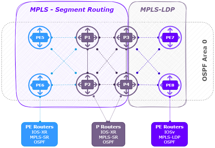
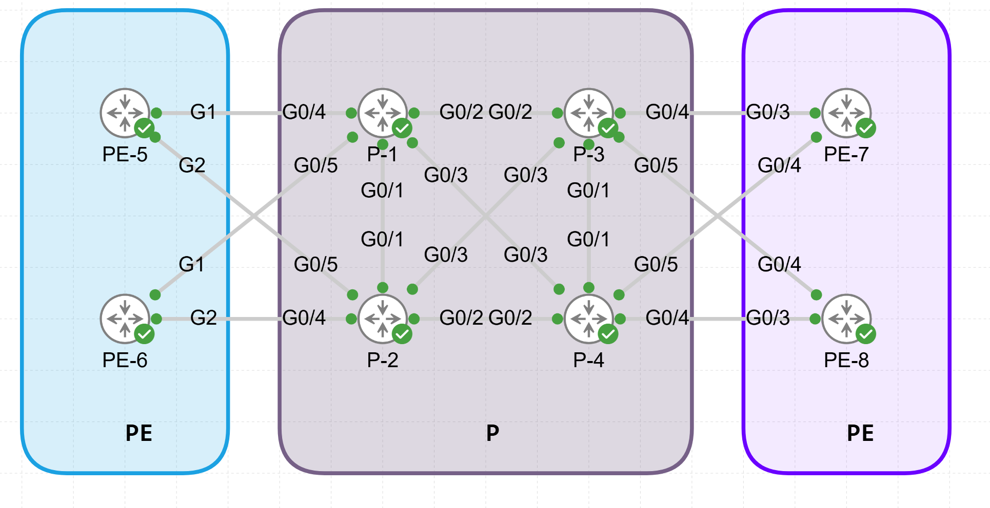
Using Cisco’s Modeling Labs (CML) I build the following MPLS-SR lab using OSPF as the IGP.

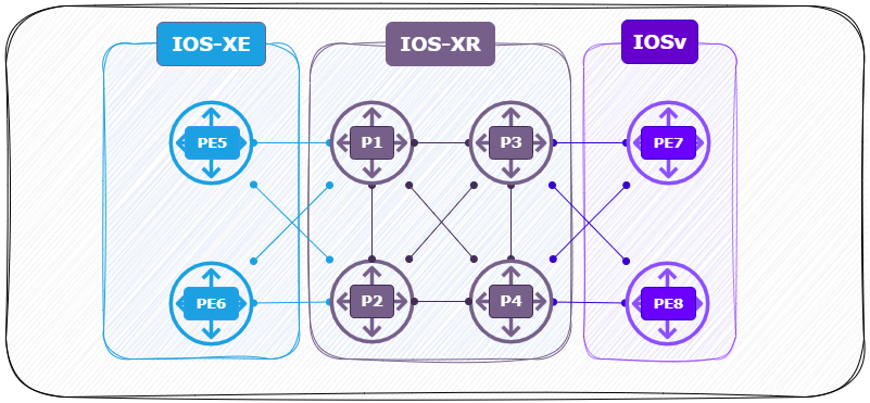
  • 2 x PE router ( Left ) (PE5, PE6) running XRv with IOS-XR.
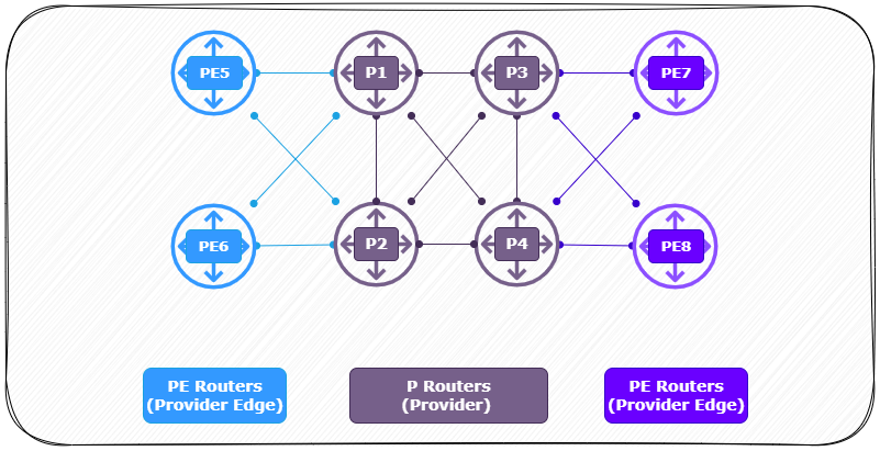
  • 4 x P router ( Center )  (P1, P2, P3, P4) running XRv with IOS-XR.
  • 2 x PE router ( Right ) (PE7, PE8) running IOSv with IOS.

Logical View:

Interfaces:

(more…)

MPLS – Segment Routing (MPLS-SR) Lab

What is MPLS Segment Routing (MPLS-SR)?


In short MPLS Segment Routing (MPLS-SR) is a modern approach to routing in MPLS (Multiprotocol Label Switching) networks. It allows for the efficient steering of traffic through predefined network segments. These segments are advertised by link-state routing protocols (IS-IS, OSPFv2, and OSPFv3) within IGP topologies. With MPLS-SR, path control and traffic engineering can be achieved without the need for protocols like LDP or RSVP-TE, which are typically used to set up traffic-engineered paths in traditional MPLS networks. These segments are stacked as labels in packet headers, allowing routers to follow predefined paths for traffic without this additional state tracking. This simplifies traffic engineering, enhances scalability, and enables efficient routing.

In this lab I will demonstrate the process of migrating from a traditional MPLS setup (using MPLS, OSPF, and LDP) to an MPLS-SR configuration on IOS-XR and IOS-XE. In this guide, you will see the configuration steps required and differences between both operating systems.
Following this, I will configure a Segment Routing Mapping Server (SRMS) to map the prefixes of IOSv routers since they don’t support MPLS-SR.

MPLS Lab Setup (Baseline)


Labs download

Two CML Labs are available for download here.

1 – Lab Pre MPLS-SR config (OSPF, MPLS, LDP).
2 – Lab Post MPLS-SR config (MPLS-SR, Prefix-sid-map, OSPF-SR).

Using Cisco’s Modeling Labs (CML) I build the following MPLS lab using OSPF and LDP neighbor relationships. 

  • 2 x PE router ( Left ) (PE5, PE6) running CSR1000v with IOS-XE.
  • 4 x P router ( Center )  (P1, P2, P3, P4) running XRv with IOS-XR.
  • 2 x PE router ( Right ) (PE7, PE8) running IOSv with IOS.

Logical View:

Interfaces:

Firmware:

(more…)

CML 2.7 – Adding the IOS-XRv image

Cisco Modeling Labs 2.7

As of Cisco Modeling Labs (CML) version 2.7, the standard IOS-XRv image has limited support and fewer features compared to the newer IOS-XRv 9000 image, which is the preferred option for IOS XR simulations in CML. The IOS-XRv image is not included in the refplat ISO and the only option available after a fresh CML 2.7 install is XRV9K. 

The IOS-XRv 9000 image includes more robust MPLS and VRF capabilities, such as successful L3 MPLS VPN implementations, making it a better choice for complex routing scenarios. However, the IOS-XRv image itself remains available with limitations, including a lack of L2 MPLS VPN support in certain scenarios.

XRv vs XRv9K resources

The only challenge with the IOS-XRv 9000 image is that it requires slightly more resources than the IOS-XRv image.

(more…)

MPLS – Segment Routing (MPLS-SR) Theory

MPLS – Segment Routing (MPLS-SR)

Multiprotocol Label Switching (MPLS) is a data-forwarding technique that uses labels to route packets along predefined paths, rather than traditional IP routing, which relies on layer-3 addresses. By attaching labels to packets, MPLS allows for high-speed data transfers and efficient traffic engineering, making it a go-to for large-scale carrier and enterprise networks.

Segment Routing (SR), is an extension for link-state IGPs (OSPF and IS-IS). Traditional MPLS forms Label Switched Paths (LSPs) through label distribution protocols such as LDP or RSVP-TE. SR simplifies this by eliminating these protocols and allowing source-based routing. In SR, the source node attaches a list of segments (labels) to the packet, guiding it through the desired path without the need for intermediate nodes to compute routing decisions. This shift enables networks to be more adaptable and scalable.

(more…)