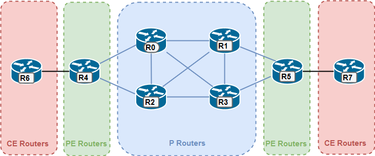
- P Routers – Provider routers
- MPLS Core
- PE Routers – Provider Edge routers
- MPLS – IP Edge
- CE Routers – Customer Edge routers
- IP Edge
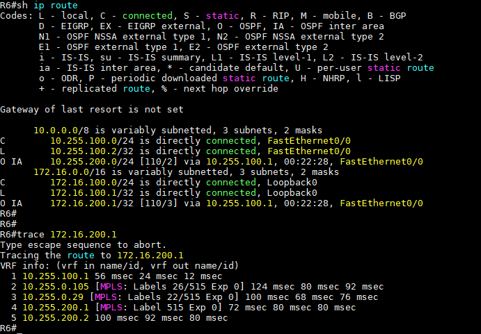
Traceroute (R6 -> R7)
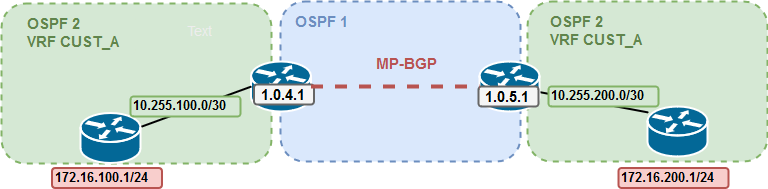
Layer 3 setup:

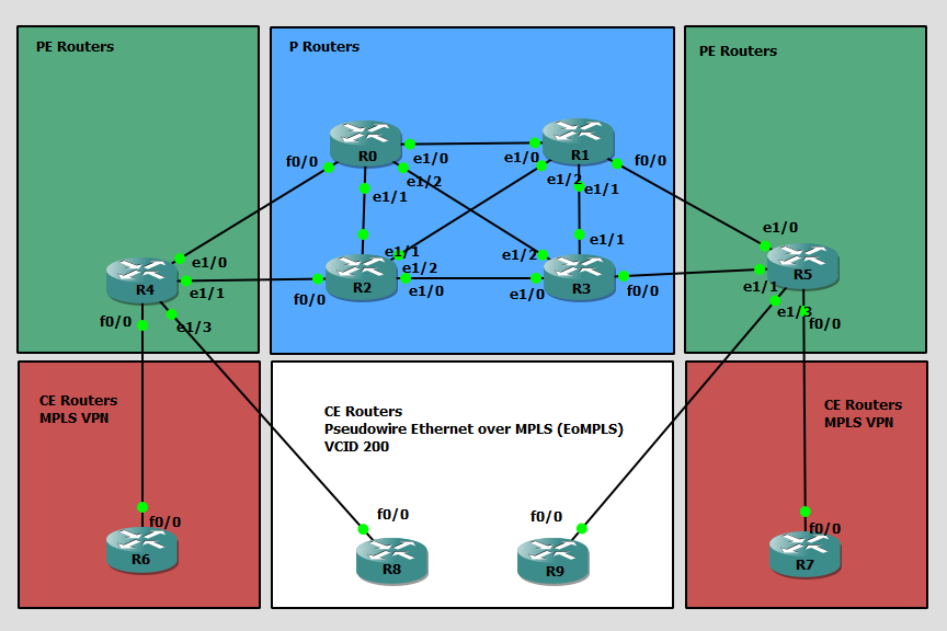
GNS3 LAB:
https://www.quisted.net/arc/datacenterdesign/lab-v-nexus7k-overlay-transport-virtualization/
License needed:

Cisco FabricPath is a Cisco NX-OS software innovation combining the plug-and-play simplicity of Ethernet with the reliability and scalability of Layer 3 routing.
Using FabricPath, you can build highly scalable Layer 2 multipath networks without the Spanning Tree Protocol. Such networks are particularly suitable for large virtualization deployments, private clouds, and high-performance computing (HPC) environments.

Activating the fabricpath feature set.
For the activation is the “ENHANCED_LAYER2.PK” license needed, or the grace-period of 120 days:


vlan 100
  mode fabricpath
  name test

interface Ethernet2/1
  switchport
  switchport mode fabricpath
  no shutdown

interface Ethernet2/2
  switchport
  switchport mode fabricpath
  no shutdown

N7K3# sh run int e2/9
interface Ethernet2/9
  switchport
  switchport access vlan 100
  no shutdown
N7K3# sh fabricpath isis

Fabricpath IS-IS domain : default
  System ID : 0026.c734.4f2f  IS-Type : L1 Fabric-Control SVI: Unknown
  SAP : 432  Queue Handle : 15
  Maximum LSP MTU: 1492
  Graceful Restart enabled. State: Inactive
  Last graceful restart status : none
  Graceful Restart holding time:60
  Metric-style : advertise(wide), accept(wide)
  Start-Mode: Complete [Start-type configuration]
  Area address(es) :
    00
  Process is up and running
  CIB ID: 1
  Interfaces supported by Fabricpath IS-IS :
    Ethernet2/1
    Ethernet2/2
    Ethernet2/5
    Ethernet2/6
    Ethernet2/10
    Ethernet2/11
  Level 1
  Authentication type and keychain not configured
  Authentication check specified
  LSP Lifetime: 1200
  L1 LSP GEN interval- Max:8000 Initial:50      Second:50
  L1 SPF Interval- Max:8000     Initial:50      Second:50
  MT-0 Ref-Bw: 400000
        Max-Path: 16
  Address family Swid unicast :
    Number of interface : 6
    Distance : 115
  L1 Next SPF: Inactive
N7K3# sh fabricpath switch-id
                        FABRICPATH SWITCH-ID TABLE
Legend: '*' - this system
        '[E]' - local Emulated Switch-id
        '[A]' - local Anycast Switch-id
Total Switch-ids: 4
=============================================================================
    SWITCH-ID      SYSTEM-ID       FLAGS         STATE    STATIC  EMULATED/
                                                                  ANYCAST
--------------+----------------+------------+-----------+--------------------
    1           0026.c751.bd2f    Primary     Confirmed Yes     No
    2           0026.c71f.a62f    Primary     Confirmed Yes     No
*   3           0026.c734.4f2f    Primary     Confirmed Yes     No
    4           0026.c7cb.4b2f    Primary     Confirmed Yes     No
N7K3# sh cdp nei
Capability Codes: R - Router, T - Trans-Bridge, B - Source-Route-Bridge
                  S - Switch, H - Host, I - IGMP, r - Repeater,
                  V - VoIP-Phone, D - Remotely-Managed-Device,
                  s - Supports-STP-Dispute

Device-ID          Local Intrfce  Hldtme Capability  Platform      Port ID
N7k1(TBC751BD00B)   Eth2/1         147    R S I s   N7K-C7018     Eth2/5
N7k1(TBC751BD00B)   Eth2/2         148    R S I s   N7K-C7018     Eth2/6
N7K2(TBC71FA600B)   Eth2/5         170    R S I s   N7K-C7018     Eth2/5
N7K2(TBC71FA600B)   Eth2/6         170    R S I s   N7K-C7018     Eth2/6
R1                  Eth2/9         134    R S I     3725          Fas0/0

Total entries displayed: 5
N7K3# sh fab
fabric       fabricpath
N7K3# sh fabri
fabric       fabricpath
N7K3# sh fabricpath route
FabricPath Unicast Route Table
'a/b/c' denotes ftag/switch-id/subswitch-id
'[x/y]' denotes [admin distance/metric]
ftag 0 is local ftag
subswitch-id 0 is default subswitch-id


FabricPath Unicast Route Table for Topology-Default

0/3/0, number of next-hops: 0
        via ---- , [60/0], 0 day/s 03:03:28, local
1/1/0, number of next-hops: 2
        via Eth2/1, [115/400], 0 day/s 03:01:13, isis_fabricpath-default
        via Eth2/2, [115/400], 0 day/s 03:01:13, isis_fabricpath-default
1/2/0, number of next-hops: 2
        via Eth2/5, [115/400], 0 day/s 03:00:59, isis_fabricpath-default
        via Eth2/6, [115/400], 0 day/s 03:00:59, isis_fabricpath-default
1/4/0, number of next-hops: 4
        via Eth2/1, [115/800], 0 day/s 03:00:59, isis_fabricpath-default
        via Eth2/2, [115/800], 0 day/s 03:00:59, isis_fabricpath-default
        via Eth2/5, [115/800], 0 day/s 03:00:59, isis_fabricpath-default
        via Eth2/6, [115/800], 0 day/s 03:00:59, isis_fabricpath-default
A VDC can be used to virtualize the device itself, presenting the physical switch as multiple logical devices. Within that VDC it can contain its own unique and independent set of VLANs and VRFs. Each VDC can have assigned to it physical ports, thus allowing for the hardware data plane to be virtualized as well. Within each VDC, a separate management domain can manage the VDC itself, thus allowing the management plane itself to also be virtualized.
Create a new VDC:
N7k1(config)# vdc N5K1
N7k1(config-vdc)#
N7k1# switchto vdc N5K1
Show allocated interfaces:
switch# show vdc membership

vdc_id: 0 vdc_name: switch interfaces:

        Ethernet2/1           Ethernet2/2           Ethernet2/3
        Ethernet2/4           Ethernet2/5           Ethernet2/6
        Ethernet2/7           Ethernet2/8           Ethernet2/9
        Ethernet2/10          Ethernet2/11          Ethernet2/12
        Ethernet2/13          Ethernet2/14          Ethernet2/15
        Ethernet2/16          Ethernet2/17          Ethernet2/18
        Ethernet2/19          Ethernet2/20          Ethernet2/21
        Ethernet2/22          Ethernet2/23          Ethernet2/24
        Ethernet2/25          Ethernet2/26          Ethernet2/27
        Ethernet2/28          Ethernet2/29          Ethernet2/30
        Ethernet2/31          Ethernet2/32          Ethernet2/33
        Ethernet2/34          Ethernet2/35          Ethernet2/36
        Ethernet2/37          Ethernet2/38          Ethernet2/39
        Ethernet2/40          Ethernet2/41          Ethernet2/42
        Ethernet2/43          Ethernet2/44          Ethernet2/45
        Ethernet2/48

vdc_id: 1 vdc_name: N5K1

        Ethernet2/47
Allocate interfaces:
N7k1(config)#vdc N5K1
N7k1(config-vdc)#allocate interface e2/1 - 12


| Nexus 7000/7700 | Nexus 5500/5600 | Nexus 2000 ( FEX ) | ||
|---|---|---|---|---|
| 1/10/40/100Gbps | 1/10/40Gbps | 1/10/40Gbps Fabric Extender | ||
| Layer2 and Layer3 LAN switching | Layer2 and Layer3 LAN switching | No local switching (Traffic is done by parent) | ||
| FCoE SAN Switching | FCoE SAN Switching | |||
| No native FC ports | Native FC Ports | |||
| Highly redundant | ||||
| SSO & ISSU |
https://www.cisco.com/c/en/us/products/switches/nexus-7000-series-switches/models-comparison.html
https://www.cisco.com/c/en/us/products/switches/nexus-5000-series-switches/models-comparison.html
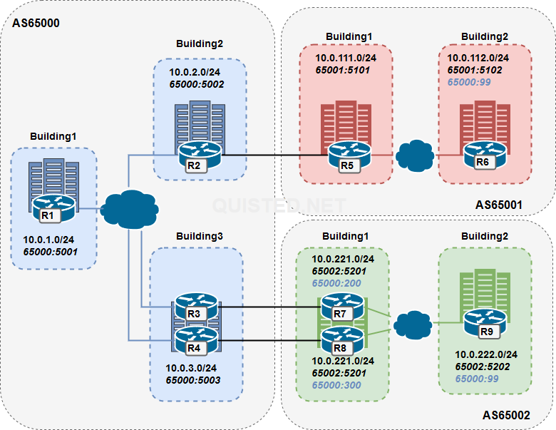
Building a case study from the ARCH FLG book; BGP communities.
The idea is to use BGP communities to influence the routing between Autonomous Systems with the following goals in mind:
| AS | Building | Subnet | Community | Description |
|---|---|---|---|---|
| AS65000 | Building 1 ( Router 1 ) | 10.0.1.0/24 | 65000:5001 | |
| AS65000 | Building 2 ( Router 2 ) | 10.0.2.0/24 | 65000:5002 | Single uplink to AS65001 |
| AS65000 | Building 3 ( Router 3 ) | 10.0.3.0/24 | 65000:5003 | Double uplink to AS65002 |
| AS65000 | Building 3 ( Router 4 ) | 10.0.3.0/24 | 65000:5003 | Double uplink to AS65002 |
| AS65001 | Building 1 ( Router 5 ) | 10.0.111.0/24 | 65001:5102 | |
| AS65001 | Building 2 ( Router 6 ) | 10.0.112.0/24 | 65001:5102 65000:99 | Community 65000:99 is used for no-export |
| AS65002 | Building 1 ( Router 7 ) | 10.0.221.0/24 | 65002:5202 65000:200 | 65000:200 is used for local preference 200 in AS65000 |
| AS65002 | Building 1 ( Router 8 ) | 10.0.221.0/24 | 65002:5201 65000:300 | 65000:300 is used for local preference 300 in AS65000 |
| AS65002 | Building 3 ( Router 9 ) | 10.0.222.0/24 | 65002:5202 65000:99 | Community 65000:99 is used for no-export |
LAB:
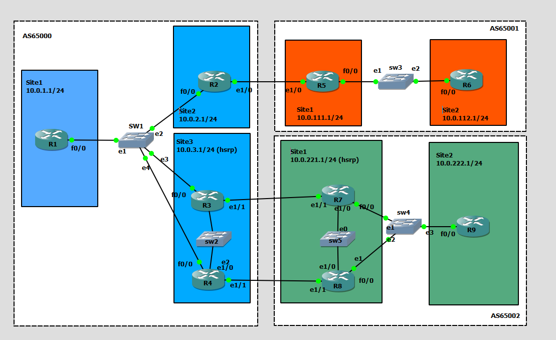
LAYER3:
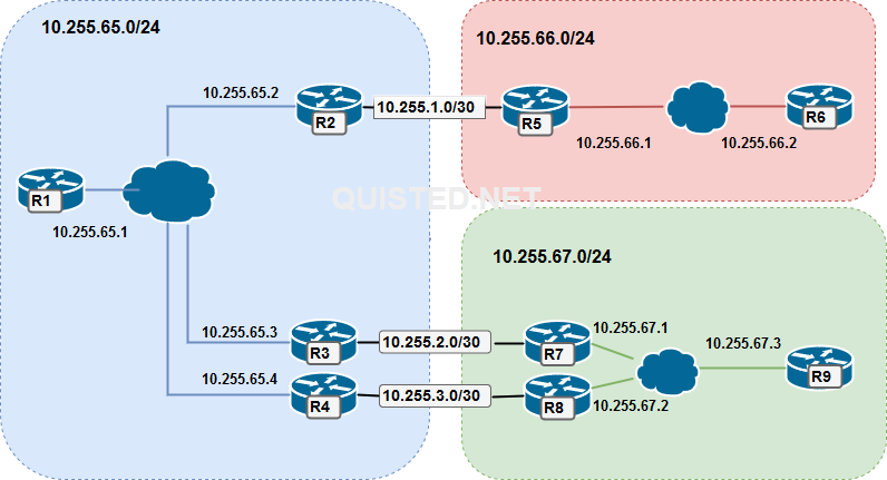
AS65000 :
R1# (Change the network and neighbor addresses where needed for the other routers)
router bgp 65000
 bgp log-neighbor-changes
 network 10.0.1.0 mask 255.255.255.0
 neighbor ibgp peer-group
 neighbor ibgp remote-as 65000
 neighbor ibgp next-hop-self
 neighbor ibgp send-community
 neighbor ibgp soft-reconfiguration inbound
 neighbor 10.255.65.2 peer-group ibgp
 neighbor 10.255.65.3 peer-group ibgp
 neighbor 10.255.65.4 peer-group ibgp
AS65001 :
R5# (Change the network and neighbor addresses where needed for the other routers)
router bgp 65001
 bgp log-neighbor-changes
 network 10.0.111.0 mask 255.255.255.0
 neighbor ibgp peer-group
 neighbor ibgp remote-as 65001
 neighbor ibgp next-hop-self
 neighbor ibgp send-community
 neighbor ibgp soft-reconfiguration inbound
 neighbor 10.255.1.1 remote-as 65000
 neighbor 10.255.1.1 send-community
 neighbor 10.255.66.2 peer-group ibgp
AS65002 :
R7# (Change the network and neighbor addresses where needed for the other routers)
router bgp 65002
 bgp log-neighbor-changes
 network 10.0.221.0 mask 255.255.255.0
 neighbor ibgp peer-group
 neighbor ibgp remote-as 65002
 neighbor ibgp next-hop-self
 neighbor ibgp send-community
 neighbor ibgp soft-reconfiguration inbound
 neighbor 10.255.2.1 remote-as 65000
 neighbor 10.255.2.1 send-community
 neighbor 10.255.2.1 route-map EBGP-MAP out
 neighbor 10.255.67.2 peer-group ibgp
 neighbor 10.255.67.3 peer-group ibgp
R9#:
access-list 101 permit ip host 10.0.222.0 host 255.255.255.0
!
route-map TAGROUTE permit 10
 match ip address 101                    # MATCH THE ROUTES YOU WANT TO TAG
 set community 65000:99 65002:5202       # SET COMMUNITIES 65000:99 (no export) and 65000:5202 ( site ID)

Router bgp 65002
- snip -
neighbor ibgp route-map TAGROUTE out     # APPLY ROUTEMAP ON OUTGOING ROUTES TOWARDS R7 + R8
- snap -
Verify on R7 and R8:
R7#sh ip bgp 10.0.222.0
BGP routing table entry for 10.0.222.0/24, version 3
Paths: (1 available, best #1, table default)
  Advertised to update-groups:
     9
  Refresh Epoch 1
  Local, (received & used)
    10.255.67.3 from 10.255.67.3 (10.0.222.1)
      Origin IGP, metric 0, localpref 100, valid, internal, best
      Community: 65000:99 65002:5202
      rx pathid: 0, tx pathid: 0x0
R7:
access-list 101 permit ip host 10.0.221.0 host 255.255.255.0
!
route-map EBGP-MAP permit 10
 match ip address 101
 set community 65000:200 65002:5101
!
route-map EBGP-MAP permit 20
!
Router bgp 65002:
neighbor 10.255.2.1 route-map EBGP-MAP out

R8:
access-list 101 permit ip host 10.0.221.0 host 255.255.255.0
!
route-map EBGP-MAP permit 10
 match ip address 101
 set community 65000:300 65002:5101
!
route-map EBGP-MAP permit 20
!
Router bgp 65002:
neighbor 10.255.3.1 route-map EBGP-MAP out
What this will accomplish is that a local pref community is send to AS65000 with resulting values of 200 for R7 and 300 for R8 for the 10.0.221.0/24 route.
R3# and R4#:
ip community-list 1 permit 65000:99        # The no-export community from R6 and R9
ip community-list 2 permit 65000:200       # The localpref community for value 200
ip community-list 3 permit 65000:300       # The localpref community for value 300
!
route-map TAG-IN permit 10
 match community 1
 set community no-export
!
route-map TAG-IN permit 20
 match community 2
 set local-preference 200
!
route-map TAG-IN permit 30
 match community 3
 set local-preference 300
!
route-map TAG-IN permit 40                  # This to allow all other routes if there were any.

router bgp 65000
 neighbor 10.255.3.2 route-map TAG-IN in
This will give R4 a higher local pref (300) for route 10.0.221.0/24 towards R8. Resulting in the following result from R3’s prespective:
R3#sh ip route 10.0.221.1
Routing entry for 10.0.221.0/24
  Known via "bgp 65000", distance 200, metric 0
  Tag 65002, type internal
  Last update from 10.255.65.4 03:51:18 ago
  Routing Descriptor Blocks:
  * 10.255.65.4, from 10.255.65.4, 03:51:18 ago        # R4 is the next hop
      Route metric is 0, traffic share count is 1
      AS Hops 1
      Route tag 65002
      MPLS label: none


R3#sh ip bgp 10.0.221.0
BGP routing table entry for 10.0.221.0/24, version 7
Paths: (2 available, best #1, table default)
  Advertised to update-groups:
     9
  Refresh Epoch 1
  65002, (received & used)
    10.255.65.4 from 10.255.65.4 (10.255.65.4)
      Origin IGP, metric 0, localpref 300, valid, internal, best
      Community: 65000:300 65002:5101
      rx pathid: 0, tx pathid: 0x0
  Refresh Epoch 1
  65002
    10.255.2.2 from 10.255.2.2 (10.255.67.1)
      Origin IGP, metric 0, localpref 200, valid, external
      Community: 65000:200 65002:5101
      rx pathid: 0, tx pathid: 0
If all goes well we shouldn’t see the 10.0.112.0/24 and 10.0.222.0/24 routes exported through AS65000 ( And we don’t );
R1#sh ip route
-
      10.0.0.0/8 is variably subnetted, 10 subnets, 2 masks
C        10.0.1.0/24 is directly connected, Loopback0
L        10.0.1.1/32 is directly connected, Loopback0
B        10.0.2.0/24 [200/0] via 10.255.65.2, 03:36:08
B        10.0.3.0/24 [200/0] via 10.255.65.3, 03:36:07
B        10.0.111.0/24 [200/0] via 10.255.65.2, 03:36:08
B        10.0.112.0/24 [200/0] via 10.255.65.2, 03:36:08        #AS6500 Sees the AS65001 route
B        10.0.221.0/24 [200/0] via 10.255.65.4, 03:36:07
B        10.0.222.0/24 [200/0] via 10.255.65.3, 03:36:07        #AS6500 Sees the AS65002 route
C        10.255.65.0/24 is directly connected, FastEthernet0/0
L        10.255.65.1/32 is directly connected, FastEthernet0/0

R6#sh ip route
      10.0.0.0/8 is variably subnetted, 9 subnets, 2 masks
B        10.0.1.0/24 [200/0] via 10.255.66.1, 03:37:08
B        10.0.2.0/24 [200/0] via 10.255.66.1, 03:37:08
B        10.0.3.0/24 [200/0] via 10.255.66.1, 03:36:39
B        10.0.111.0/24 [200/0] via 10.255.66.1, 00:00:03
C        10.0.112.0/24 is directly connected, Loopback0
L        10.0.112.1/32 is directly connected, Loopback0
B        10.0.221.0/24 [200/0] via 10.255.66.1, 03:36:39
C        10.255.66.0/24 is directly connected, FastEthernet0/0
L        10.255.66.2/32 is directly connected, FastEthernet0/0
                                                          #AS65001 is missing the 10.0.222.0/24 route

R9#sh ip route
      10.0.0.0/8 is variably subnetted, 9 subnets, 2 masks
B        10.0.1.0/24 [200/0] via 10.255.67.1, 03:34:29
B        10.0.2.0/24 [200/0] via 10.255.67.1, 03:34:29
B        10.0.3.0/24 [200/0] via 10.255.67.1, 03:34:29
B        10.0.111.0/24 [200/0] via 10.255.67.1, 03:34:29
B        10.0.221.0/24 [200/0] via 10.255.67.1, 03:41:11
C        10.0.222.0/24 is directly connected, Loopback0
L        10.0.222.1/32 is directly connected, Loopback0
C        10.255.67.0/24 is directly connected, FastEthernet0/0
L        10.255.67.3/32 is directly connected, FastEthernet0/0
                                                         #AS65002 is missing the 10.0.112.0/24 route
Next up, Datacenter!

https://learningcontent.cisco.com/cln_storage/text/cln/marketing/exam-topics/200-150-dcicn.pdf
https://learningcontent.cisco.com/cln_storage/text/cln/marketing/exam-topics/200-155-dcict.pdf