Building a case study from the ARCH FLG book; BGP communities.
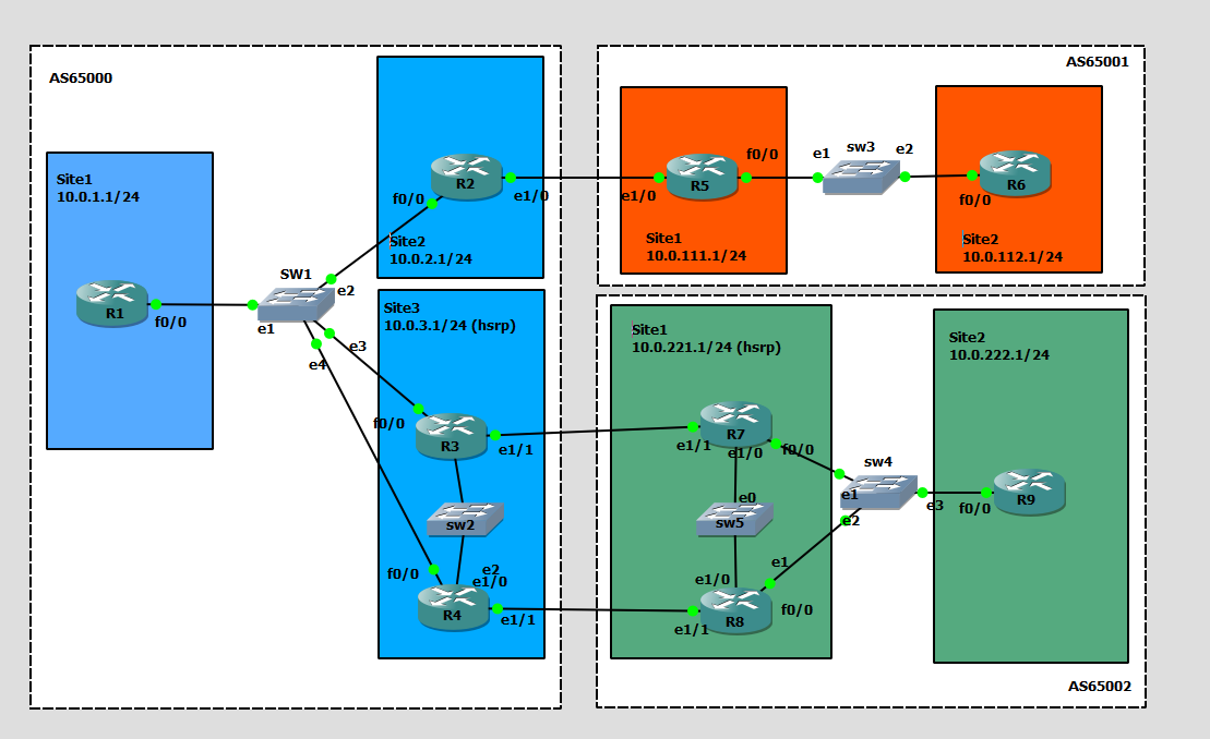
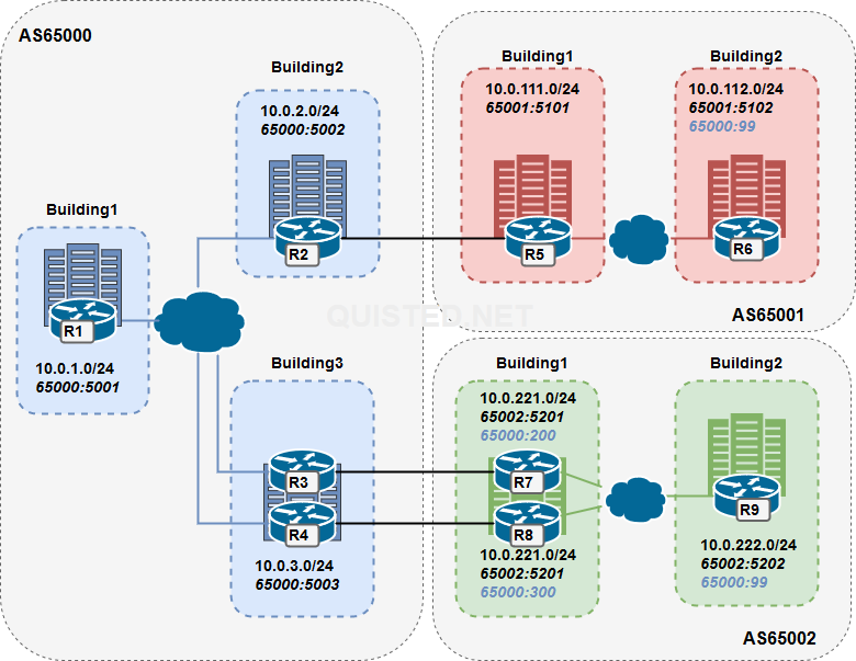
The idea is to use BGP communities to influence the routing between Autonomous Systems with the following goals in mind:
- Configure communities to tag the routes per building on each AS.
- Configure communities as no-export so the routes of AS65001.building2 and AS65002.building2 are not exported through AS65000.
- The routes will be tagged on R6 and R9 with community 65000:99 and processed on the AS boundry.
- The routes of AS65001.building1 and AS65002.building1 are allowed to be exported.
- Configure communities so that R7 and R8 can set their local preference on the AS65000 side.
- The routes will be tagged on R7 will be tagged with 65000:200 resulting in a local-preference of 200.
- The routes will be tagged on R8 will be tagged with 65000:300 resulting in a local-preference of 300.
| AS | Building | Subnet | Community | Description |
| AS65000 | Building 1 ( Router 1 ) | 10.0.1.0/24 | 65000:5001 | |
| AS65000 | Building 2 ( Router 2 ) | 10.0.2.0/24 | 65000:5002 | Single uplink to AS65001 |
| AS65000 | Building 3 ( Router 3 ) | 10.0.3.0/24 | 65000:5003 | Double uplink to AS65002 |
| AS65000 | Building 3 ( Router 4 ) | 10.0.3.0/24 | 65000:5003 | Double uplink to AS65002 |
| | | | |
| AS65001 | Building 1 ( Router 5 ) | 10.0.111.0/24 | 65001:5102
| |
| AS65001 | Building 2 ( Router 6 ) | 10.0.112.0/24 | 65001:5102
65000:99 | Community 65000:99 is used for no-export |
| | | | |
| AS65002 | Building 1 ( Router 7 ) | 10.0.221.0/24 | 65002:5202
65000:200 | 65000:200 is used for local preference 200 in AS65000 |
| AS65002 | Building 1 ( Router 8 ) | 10.0.221.0/24 | 65002:5201
65000:300 | 65000:300 is used for local preference 300 in AS65000 |
| AS65002 | Building 3 ( Router 9 ) | 10.0.222.0/24 | 65002:5202
65000:99 | Community 65000:99 is used for no-export |
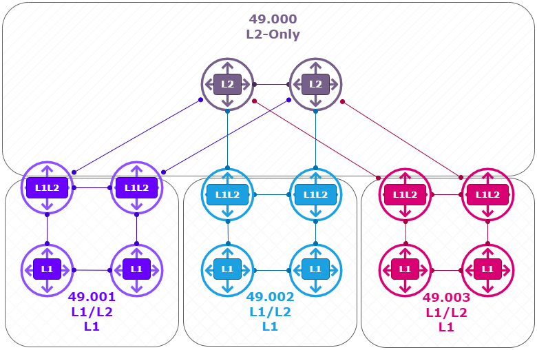
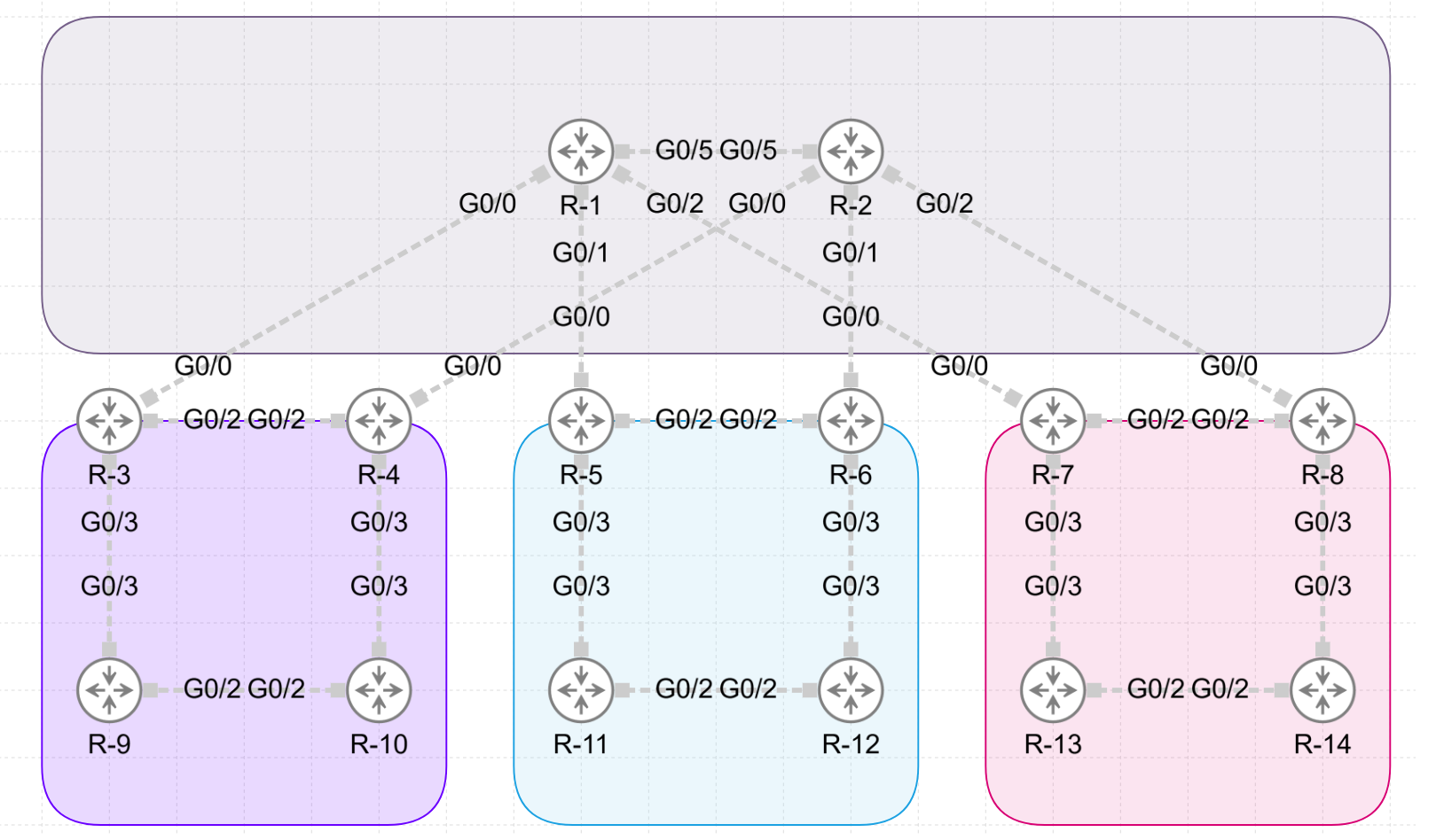
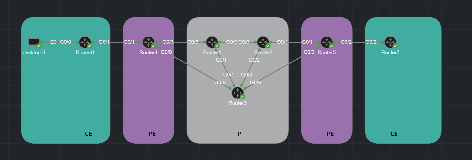
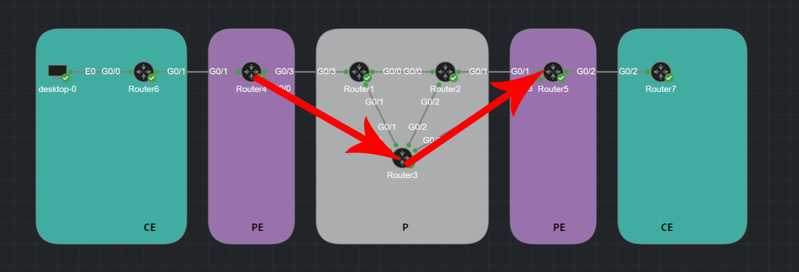
LAB:
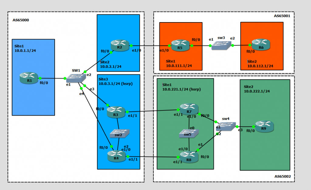
LAYER3:
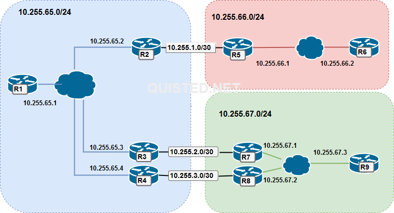
BGP Configuration:
AS65000 :
R1# (Change the network and neighbor addresses where needed for the other routers)
router bgp 65000
 bgp log-neighbor-changes
 network 10.0.1.0 mask 255.255.255.0
 neighbor ibgp peer-group
 neighbor ibgp remote-as 65000
 neighbor ibgp next-hop-self
 neighbor ibgp send-community
 neighbor ibgp soft-reconfiguration inbound
 neighbor 10.255.65.2 peer-group ibgp
 neighbor 10.255.65.3 peer-group ibgp
 neighbor 10.255.65.4 peer-group ibgp
AS65001 :
R5# (Change the network and neighbor addresses where needed for the other routers)
router bgp 65001
 bgp log-neighbor-changes
 network 10.0.111.0 mask 255.255.255.0
 neighbor ibgp peer-group
 neighbor ibgp remote-as 65001
 neighbor ibgp next-hop-self
 neighbor ibgp send-community
 neighbor ibgp soft-reconfiguration inbound
 neighbor 10.255.1.1 remote-as 65000
 neighbor 10.255.1.1 send-community
 neighbor 10.255.66.2 peer-group ibgp
AS65002 :
R7# (Change the network and neighbor addresses where needed for the other routers)
router bgp 65002
 bgp log-neighbor-changes
 network 10.0.221.0 mask 255.255.255.0
 neighbor ibgp peer-group
 neighbor ibgp remote-as 65002
 neighbor ibgp next-hop-self
 neighbor ibgp send-community
 neighbor ibgp soft-reconfiguration inbound
 neighbor 10.255.2.1 remote-as 65000
 neighbor 10.255.2.1 send-community
 neighbor 10.255.2.1 route-map EBGP-MAP out
 neighbor 10.255.67.2 peer-group ibgp
 neighbor 10.255.67.3 peer-group ibgp
Tagging routes on R6 and R9 (no export)
R9#:
access-list 101 permit ip host 10.0.222.0 host 255.255.255.0
!
route-map TAGROUTE permit 10
 match ip address 101                    # MATCH THE ROUTES YOU WANT TO TAG
 set community 65000:99 65002:5202       # SET COMMUNITIES 65000:99 (no export) and 65000:5202 ( site ID)

Router bgp 65002
- snip -
neighbor ibgp route-map TAGROUTE out     # APPLY ROUTEMAP ON OUTGOING ROUTES TOWARDS R7 + R8
- snap -
Verify on R7 and R8:
R7#sh ip bgp 10.0.222.0
BGP routing table entry for 10.0.222.0/24, version 3
Paths: (1 available, best #1, table default)
  Advertised to update-groups:
     9
  Refresh Epoch 1
  Local, (received & used)
    10.255.67.3 from 10.255.67.3 (10.0.222.1)
      Origin IGP, metric 0, localpref 100, valid, internal, best
      Community: 65000:99 65002:5202
      rx pathid: 0, tx pathid: 0x0
Confuring communities on R7 and R8 ( Site-ID’s and Local pref community )
R7:
access-list 101 permit ip host 10.0.221.0 host 255.255.255.0
!
route-map EBGP-MAP permit 10
 match ip address 101
 set community 65000:200 65002:5101
!
route-map EBGP-MAP permit 20
!
Router bgp 65002:
neighbor 10.255.2.1 route-map EBGP-MAP out

R8:
access-list 101 permit ip host 10.0.221.0 host 255.255.255.0
!
route-map EBGP-MAP permit 10
 match ip address 101
 set community 65000:300 65002:5101
!
route-map EBGP-MAP permit 20
!
Router bgp 65002:
neighbor 10.255.3.1 route-map EBGP-MAP out
What this will accomplish is that a local pref community is send to AS65000 with resulting values of 200 for R7 and 300 for R8 for the 10.0.221.0/24 route.
Confuring the community settings on R3 and R4 ( No export and Local pref )
R3# and R4#:
ip community-list 1 permit 65000:99        # The no-export community from R6 and R9
ip community-list 2 permit 65000:200       # The localpref community for value 200
ip community-list 3 permit 65000:300       # The localpref community for value 300
!
route-map TAG-IN permit 10
 match community 1
 set community no-export
!
route-map TAG-IN permit 20
 match community 2
 set local-preference 200
!
route-map TAG-IN permit 30
 match community 3
 set local-preference 300
!
route-map TAG-IN permit 40                  # This to allow all other routes if there were any.

router bgp 65000
 neighbor 10.255.3.2 route-map TAG-IN in
This will give R4 a higher local pref (300) for route 10.0.221.0/24 towards R8. Resulting in the following result from R3’s prespective:
R3#sh ip route 10.0.221.1
Routing entry for 10.0.221.0/24
  Known via "bgp 65000", distance 200, metric 0
  Tag 65002, type internal
  Last update from 10.255.65.4 03:51:18 ago
  Routing Descriptor Blocks:
  * 10.255.65.4, from 10.255.65.4, 03:51:18 ago        # R4 is the next hop
      Route metric is 0, traffic share count is 1
      AS Hops 1
      Route tag 65002
      MPLS label: none


R3#sh ip bgp 10.0.221.0
BGP routing table entry for 10.0.221.0/24, version 7
Paths: (2 available, best #1, table default)
  Advertised to update-groups:
     9
  Refresh Epoch 1
  65002, (received & used)
    10.255.65.4 from 10.255.65.4 (10.255.65.4)
      Origin IGP, metric 0, localpref 300, valid, internal, best
      Community: 65000:300 65002:5101
      rx pathid: 0, tx pathid: 0x0
  Refresh Epoch 1
  65002
    10.255.2.2 from 10.255.2.2 (10.255.67.1)
      Origin IGP, metric 0, localpref 200, valid, external
      Community: 65000:200 65002:5101
      rx pathid: 0, tx pathid: 0
Verifying the no-export community
If all goes well we shouldn’t see the 10.0.112.0/24 and 10.0.222.0/24 routes exported through AS65000 ( And we don’t );
R1#sh ip route
-
      10.0.0.0/8 is variably subnetted, 10 subnets, 2 masks
C        10.0.1.0/24 is directly connected, Loopback0
L        10.0.1.1/32 is directly connected, Loopback0
B        10.0.2.0/24 [200/0] via 10.255.65.2, 03:36:08
B        10.0.3.0/24 [200/0] via 10.255.65.3, 03:36:07
B        10.0.111.0/24 [200/0] via 10.255.65.2, 03:36:08
B        10.0.112.0/24 [200/0] via 10.255.65.2, 03:36:08        #AS6500 Sees the AS65001 route
B        10.0.221.0/24 [200/0] via 10.255.65.4, 03:36:07
B        10.0.222.0/24 [200/0] via 10.255.65.3, 03:36:07        #AS6500 Sees the AS65002 route
C        10.255.65.0/24 is directly connected, FastEthernet0/0
L        10.255.65.1/32 is directly connected, FastEthernet0/0

R6#sh ip route
      10.0.0.0/8 is variably subnetted, 9 subnets, 2 masks
B        10.0.1.0/24 [200/0] via 10.255.66.1, 03:37:08
B        10.0.2.0/24 [200/0] via 10.255.66.1, 03:37:08
B        10.0.3.0/24 [200/0] via 10.255.66.1, 03:36:39
B        10.0.111.0/24 [200/0] via 10.255.66.1, 00:00:03
C        10.0.112.0/24 is directly connected, Loopback0
L        10.0.112.1/32 is directly connected, Loopback0
B        10.0.221.0/24 [200/0] via 10.255.66.1, 03:36:39
C        10.255.66.0/24 is directly connected, FastEthernet0/0
L        10.255.66.2/32 is directly connected, FastEthernet0/0
                                                          #AS65001 is missing the 10.0.222.0/24 route

R9#sh ip route
      10.0.0.0/8 is variably subnetted, 9 subnets, 2 masks
B        10.0.1.0/24 [200/0] via 10.255.67.1, 03:34:29
B        10.0.2.0/24 [200/0] via 10.255.67.1, 03:34:29
B        10.0.3.0/24 [200/0] via 10.255.67.1, 03:34:29
B        10.0.111.0/24 [200/0] via 10.255.67.1, 03:34:29
B        10.0.221.0/24 [200/0] via 10.255.67.1, 03:41:11
C        10.0.222.0/24 is directly connected, Loopback0
L        10.0.222.1/32 is directly connected, Loopback0
C        10.255.67.0/24 is directly connected, FastEthernet0/0
L        10.255.67.3/32 is directly connected, FastEthernet0/0
                                                         #AS65002 is missing the 10.0.112.0/24 route