Fabricpath
Cisco FabricPath is a Cisco NX-OS software innovation combining the plug-and-play simplicity of Ethernet with the reliability and scalability of Layer 3 routing.
Using FabricPath, you can build highly scalable Layer 2 multipath networks without the Spanning Tree Protocol. Such networks are particularly suitable for large virtualization deployments, private clouds, and high-performance computing (HPC) environments.

Datacenter Design V ( TRILL, Fabric Path )
https://www.cisco.com/c/en/us/products/collateral/switches/nexus-5000-series-switches/guide_c07-690079.html
https://www.cisco.com/c/en/us/td/docs/switches/datacenter/sw/6_x/nx-os/fabricpath/configuration/guide/b-Cisco-Nexus-7000-Series-NX-OS-FP-Configuration-Guide-6x.html
- Classic Ethernet ( CE )
- Regular internet with regular flooding, regular STP, etc.
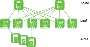
- Leaf switch
- Connects CE domain to FP domain
- Spine switch
- FP backbone switch all ports in the FP domain only
- FP Core Ports
- Links on leaf up to Spine, or Spine to Spine
- i.e. the switchport mode fabricpath links
- CE Edge Ports
- Links of leaf connecting to regular CE domain (to servers / switches)
- i.e. NOT the switchport mode fabricpath links
Activating the fabricpath feature set.
For the activation is the “ENHANCED_LAYER2.PK” license needed, or the grace-period of 120 days:


vlan 100
  mode fabricpath
  name test

interface Ethernet2/1
  switchport
  switchport mode fabricpath
  no shutdown

interface Ethernet2/2
  switchport
  switchport mode fabricpath
  no shutdown

N7K3# sh run int e2/9
interface Ethernet2/9
  switchport
  switchport access vlan 100
  no shutdown
N7K3# sh fabricpath isis

Fabricpath IS-IS domain : default
  System ID : 0026.c734.4f2f  IS-Type : L1 Fabric-Control SVI: Unknown
  SAP : 432  Queue Handle : 15
  Maximum LSP MTU: 1492
  Graceful Restart enabled. State: Inactive
  Last graceful restart status : none
  Graceful Restart holding time:60
  Metric-style : advertise(wide), accept(wide)
  Start-Mode: Complete [Start-type configuration]
  Area address(es) :
    00
  Process is up and running
  CIB ID: 1
  Interfaces supported by Fabricpath IS-IS :
    Ethernet2/1
    Ethernet2/2
    Ethernet2/5
    Ethernet2/6
    Ethernet2/10
    Ethernet2/11
  Level 1
  Authentication type and keychain not configured
  Authentication check specified
  LSP Lifetime: 1200
  L1 LSP GEN interval- Max:8000 Initial:50      Second:50
  L1 SPF Interval- Max:8000     Initial:50      Second:50
  MT-0 Ref-Bw: 400000
        Max-Path: 16
  Address family Swid unicast :
    Number of interface : 6
    Distance : 115
  L1 Next SPF: Inactive
N7K3# sh fabricpath switch-id
                        FABRICPATH SWITCH-ID TABLE
Legend: '*' - this system
        '[E]' - local Emulated Switch-id
        '[A]' - local Anycast Switch-id
Total Switch-ids: 4
=============================================================================
    SWITCH-ID      SYSTEM-ID       FLAGS         STATE    STATIC  EMULATED/
                                                                  ANYCAST
--------------+----------------+------------+-----------+--------------------
    1           0026.c751.bd2f    Primary     Confirmed Yes     No
    2           0026.c71f.a62f    Primary     Confirmed Yes     No
*   3           0026.c734.4f2f    Primary     Confirmed Yes     No
    4           0026.c7cb.4b2f    Primary     Confirmed Yes     No
N7K3# sh cdp nei
Capability Codes: R - Router, T - Trans-Bridge, B - Source-Route-Bridge
                  S - Switch, H - Host, I - IGMP, r - Repeater,
                  V - VoIP-Phone, D - Remotely-Managed-Device,
                  s - Supports-STP-Dispute

Device-ID          Local Intrfce  Hldtme Capability  Platform      Port ID
N7k1(TBC751BD00B)   Eth2/1         147    R S I s   N7K-C7018     Eth2/5
N7k1(TBC751BD00B)   Eth2/2         148    R S I s   N7K-C7018     Eth2/6
N7K2(TBC71FA600B)   Eth2/5         170    R S I s   N7K-C7018     Eth2/5
N7K2(TBC71FA600B)   Eth2/6         170    R S I s   N7K-C7018     Eth2/6
R1                  Eth2/9         134    R S I     3725          Fas0/0

Total entries displayed: 5
N7K3# sh fab
fabric       fabricpath
N7K3# sh fabri
fabric       fabricpath
N7K3# sh fabricpath route
FabricPath Unicast Route Table
'a/b/c' denotes ftag/switch-id/subswitch-id
'[x/y]' denotes [admin distance/metric]
ftag 0 is local ftag
subswitch-id 0 is default subswitch-id


FabricPath Unicast Route Table for Topology-Default

0/3/0, number of next-hops: 0
        via ---- , [60/0], 0 day/s 03:03:28, local
1/1/0, number of next-hops: 2
        via Eth2/1, [115/400], 0 day/s 03:01:13, isis_fabricpath-default
        via Eth2/2, [115/400], 0 day/s 03:01:13, isis_fabricpath-default
1/2/0, number of next-hops: 2
        via Eth2/5, [115/400], 0 day/s 03:00:59, isis_fabricpath-default
        via Eth2/6, [115/400], 0 day/s 03:00:59, isis_fabricpath-default
1/4/0, number of next-hops: 4
        via Eth2/1, [115/800], 0 day/s 03:00:59, isis_fabricpath-default
        via Eth2/2, [115/800], 0 day/s 03:00:59, isis_fabricpath-default
        via Eth2/5, [115/800], 0 day/s 03:00:59, isis_fabricpath-default
        via Eth2/6, [115/800], 0 day/s 03:00:59, isis_fabricpath-default